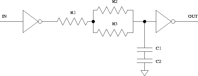
- In terms of
 ,
,  ,
,  ,
,  , and
, and  , write the
equation of the circuit's time constant.
, write the
equation of the circuit's time constant. - Suppose that all resistors are 1k
 and all capacitors are
0.1
and all capacitors are
0.1  F. What is the time constant?
 - Assume inverter output is either 0V or 5V, and the inverter threshold voltage (where it switches from low to high) is 1.6V. If the input signal goes from high to low instantaneously, how much latter will the output signal go from high to low? How about if the input signal goes from low to high? Use the equation for charging and discharging an RC circuit to find when it passes 1.6V.
- If the input signal is square wave with period of 0.4ms, describe and diagram the output.
- Suppose instead that the inverter has typical output voltages of
 , and
, and  . How does this change the
previous problem? (One way to deal with the non-zero starting point
on charging the RC circuit is to subtract off the time it takes to
rise from 0V to 0.25V. When dealing with exponentials, always
check the boundary conditions of t=0 and
. How does this change the
previous problem? (One way to deal with the non-zero starting point
on charging the RC circuit is to subtract off the time it takes to
rise from 0V to 0.25V. When dealing with exponentials, always
check the boundary conditions of t=0 and  to catch simple
errors.)
to catch simple
errors.)
          Lack of staples      -2
          Rough paper edges    -2
          No name              -5
          Hard to read writing -2
          Answers only-no work -20 (or more)

          Typeset              +3
          Graph Paper          +1
          Straightedge         +1
          Neat writing         +1
          Clearly marked answers +1
          Clear writing explaining steps or design +2