L E N S M O D E L I N G
Primary Project Goals:
- Distort image perspective using a translational lens modeling system
- Animate interpolation between two selected lenses
- Create a set of standard lenses that can be selected, and allow the user to create dynamic lenses by adjusting lens functions.
Concept:
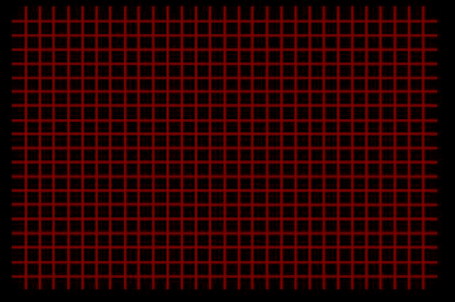
It is possible to simulate the effect of an optic lens on an image by applying functions that have been normalized to constrict thier values to plus or minus 1 in the x and y directions. Worthy canditates for such functions should fill the entire range, passing diagonally through the origin and occupying the first and third quadrants (functions occupying the second and fourth quadrants will flip the image). The images below demonstrate two such functions. The first, the linear function with slope 1 represents a lens without distortion, while the second is the sin function with its input multiplied by PI/2. The x value of the function represents coordinates of the undistorted image, and the y value represents the distorted coordinates. Below the graphs are the results of applying the respective functions to an image of a square grid in the x and y directions.
 Undistorted Images:
These stock images are provided as reference to depomstrate the effects of the following lenses.
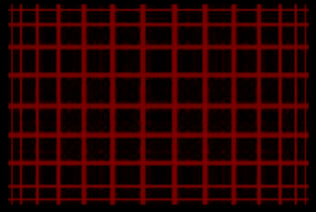
Undistorted Images:
These stock images are provided as reference to depomstrate the effects of the following lenses.
 Quads are your friend:

fisheye lens applied to an image rendered using points

wide angle lens applied to an image rendered using quads
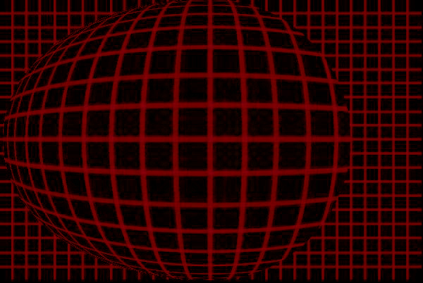
It is important to choose functions restricted to the first and third quadrants:
These images were generated by normalizing the cosine function (which occupies the first and second quadrants). Notice the information loss.
Rectilinear Cosine Lens Applied to Grid

Rectilinear Cosine Lens Applied to Image
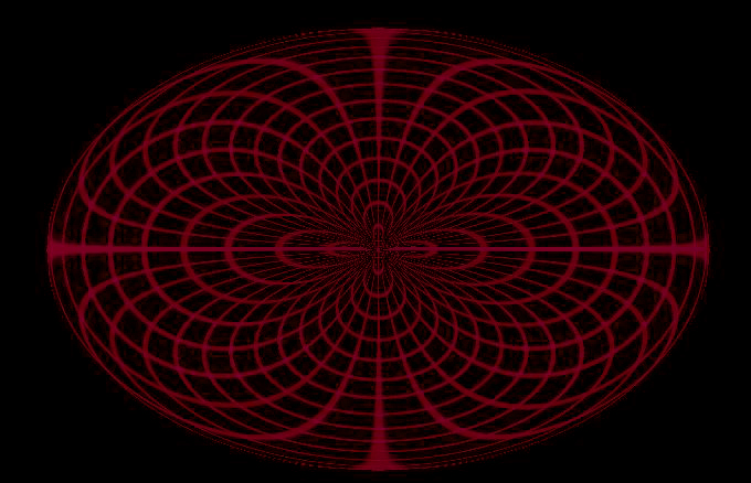
Although, when applied radially, functions such as cosine can produce interesting results. Mirroring the effect across the x-axis enhances this result even further.
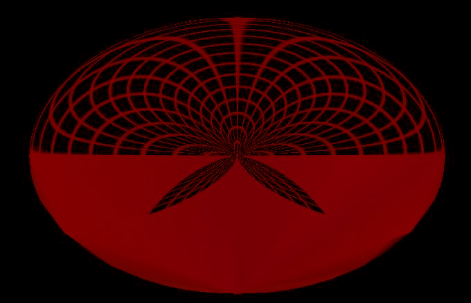
Radial Cosine Lens Applied to Grid

Radial Cosine Lens Applied to Image
Radial Cosine Lens Mirrored Across the X-Axis
The case for shaders
Given this project to do over, I would take a shader approach instead of performing the translations directly in opengl. The first reason is that using shaders would result in a substantial performance boost. The second reason is that the purely opengl approach has severe limitations when trying to extend it to 3D models, as the following images demonstrate. In the first, notice the sawtooth artifacts. These artifacts come from translating the polygon vertices and leaving fragment interpolation to the hardware. The second shows distorted normals (which could actually be fixed through recalculation [notice the likeness of a pirate in the middle left]).

3D Model With Distortion
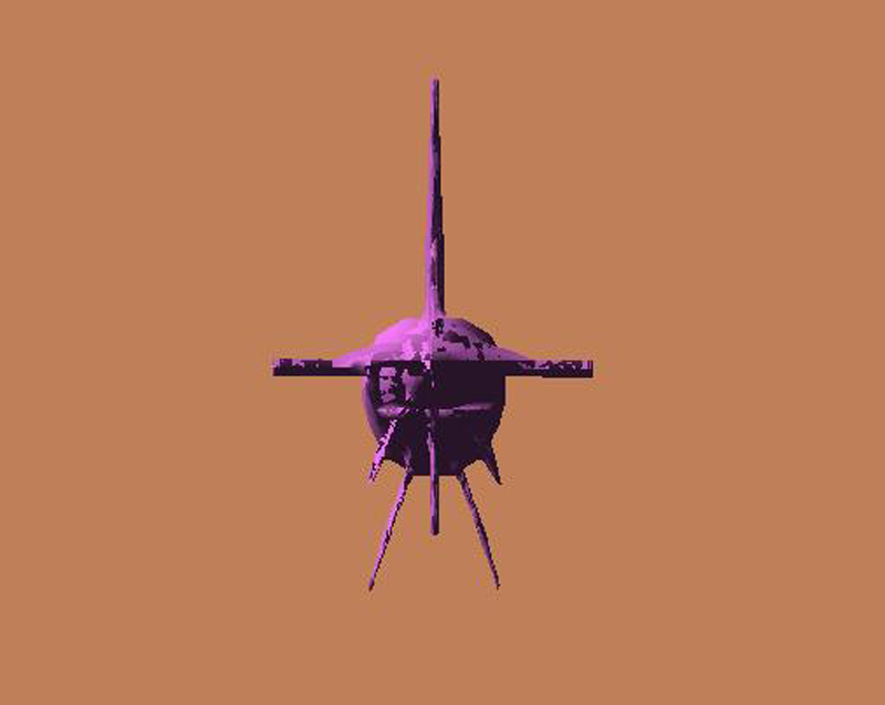
Translation Distortion corrupts normals
And now for some stuff that's not broken
Lens with a smaller radius and a bias in the negative x direction
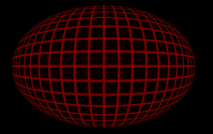
Fisheye Lens Applied to Grid

Lens with a smaller radius applied to image

Square lens applied to image
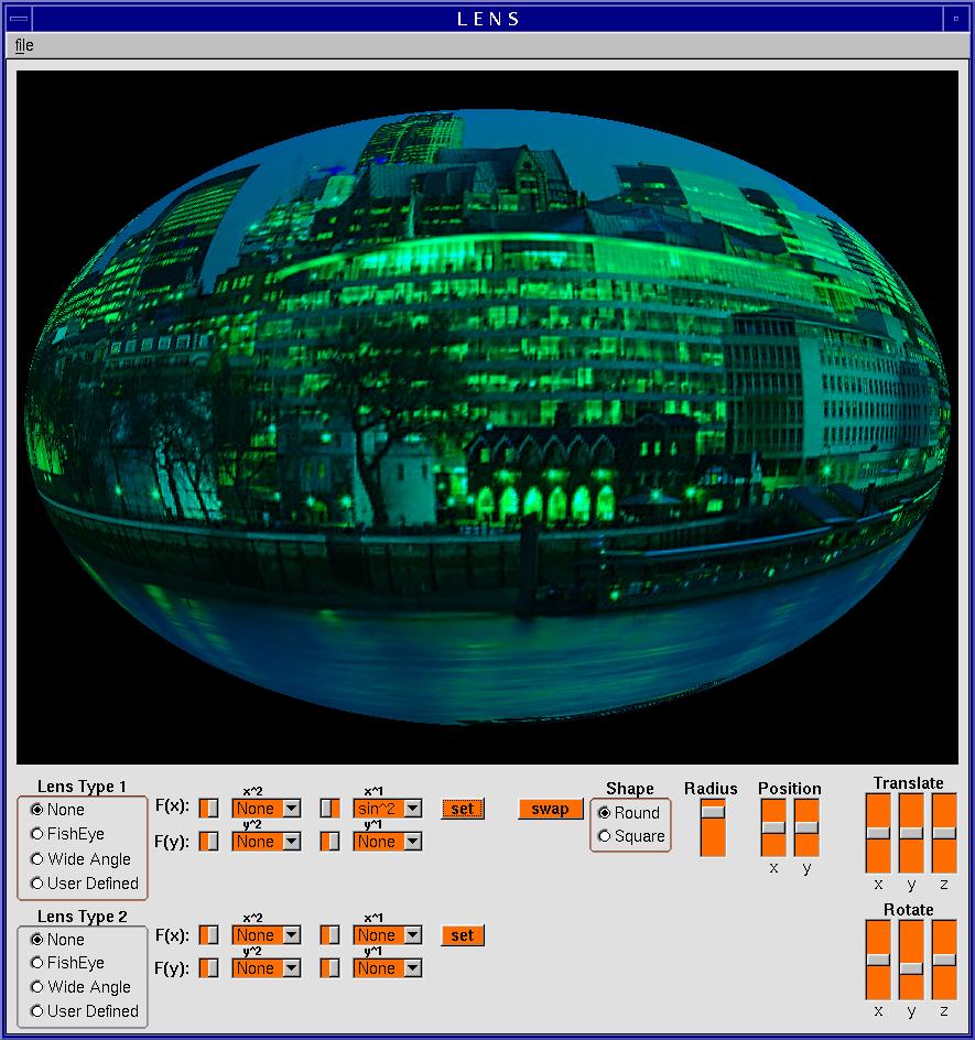
My stellar Gui