Ryan Connors
Joseph Bernay
CMPS 160 : Final Project : WebMod
Spring 2015, UCSC
Scroll down for mini user guides
Project Description:
WebMod is a webGL-based 3D modeling program capable of supporting small-scale pre-visualization models and renders with a lean user interface and render times that achieve linear complexity.
Components and Features:
Global Data Tables and Linear Rendering Runtime Complexity:
Storing the vertices at the mesh level facilitates easier concatenation of mesh tables during merge operations. All mesh data is stored in a global table. Rendering simply steps through this table. During a normal render, a picking render is created for pixel data storage, then a real render is achieved. If Polygonal Editing Mode is active, a second picking render occurs using distinct colors for each polygon of each mesh. In this manner, both Mesh and Poly-picking are achieved.
Vertex/Triangle/Polygon/Mesh Class Hierarchy:
A family of objects is used to represent graphical objects. At the head of this family is the Mesh Object, which contains all data pertinent to rendering. It contains the color for use in picking, a material color, and a vertex table which all polygon objects reference by key/index. It also contain a data structure of polygon child objects that construct the base mesh object. The polygon class uses a list of vertices referencing key values from the parent mesh object vertex table. Finally, the polygon contains a table of triangle objects that are created through a triangulation algorithm. The triangles will in turn contain a list of keys referencing vertices stored in the Mesh vertex table. Ultimately the triangles are the objects rendered.
Primitive Collection:
The modelling program contains buttons that will allow for the creation of rectangular prisms, spheres, pyramids, cylinders, cones, and toroids. Each button will create its corresponding complete mesh and its associated objects at the origin of the scene for manipulation and transformation by the user.
Runtime Mesh Editing and Vertex Manipulation:
Polygons are selectable and their vertices can be manipulated during the program's execution through the use of polygon scaling and translation operations. The polygon utilizes a color table for picking. Once a polygon has been picked, its face may be scaled, translated axially on its normal, extruded, or deleted. These operations will all alter the vertex world coordinates.
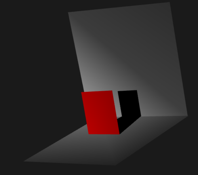
Mesh Merging:
Meshes can be merged additively to create an entirely new mesh object. First, the object is checked for tolerances, and then, if those tolerances are met, the merge operation is performed. It will merge the vertex tables and provide additional polygons that join the two faces being merged. Currently this is supported only for selecting two faces and clicking the merge button. The angle of the face normals will cause different merge results. Objects in a state of collision should not be merged. This was one of the only ways to scale the merge problem into one conquerable within the scope of this time frame.
User-selected Shading Using State-based Code Paths:
The user can select the types of shading desired for the scene to undergo by the use of html buttons. These buttons will change GLSL values in the shader code, and these values will be sensed by GLSL control paths. In this manner, the actual final shading will undergo a user-defined process.
Anti-aliasing and Post-rasterization Effects:
Time did not permit the implementation of this feature. It was marked as an optional (if time permits) feature in the initial proposal.
Model Data IO:
Model vertex and poly data can be exported to an html text area where the data can be stored in a notepad and piped back in at a later time. Clicking the generate button will generate the poly/coord files for the currently selected Mesh. Clicking import will accept the data (which is assumed good) from the text area and create a new mesh object. You will need to scale this new mesh appropriately if importing from another object coordinate system.
Mini Users Guide:
This guide has been formatted from the Graders' Perspective when walking linearly through proposal features.
Data Tables and Linear Rendering Runtime:
The number of render operations is directly proportional to the complexity of the set of Mesh Vertices N. This in turn is dependent upon the number of triangles that comprise a scene, T. For each triangle added, the number of vertices to process increases by 3.
Vertex/Triangle/Polygon/Mesh Class Family:
The Class Family is detailed below. The Mesh object contains all data required to render itself. On a call to it's render function, all appropriate flags and values are set on the GPU and then rendered appropriately. Each Mesh is comprised of a set of Polygon objects. Each Polygon object breaks itself into a set of Triangle objects and pushes the result to its parent Mesh's triangle table. These Triangles are then pushed to the buffer when the pushBuffer function is called.
Fig 1. The Mesh, Polygon, Triangle, Vector Class Interaction:
Each object also contains support functions that are used during render calculations. For example, the Triangle object has a function that will return its normal. The Mesh object is capable of breaking its own Polygons into Triangles and pushing its data to the buffer.
Primitive Collection:
The primitive collection consists of a Cube, Pyramid, Sphere, Cylinder, Cone, and Toroid. You can use the Primitive Creation UI under the viewport to create these meshes. These are created with global functions that generate vertex and poly lists uses a standardized object space system. This data is then 'parsed' into a new Mesh object in the same manner in which it would be read from a file.
Runtime Mesh Editing and Vertex Manipulation:
The meshes can be edited during runtime by selecting the polygon you wish to edit. Ensure PolyMode is active by checking the button in Mesh Edit UI Segment. Then, click the polygon you wish to edit. Hold down the S key to scale this polygon, Hold down Z to shift this polygon on its normal axis. Click the Delete Polygon Button to remove this face. Click on the Extrude Polygon button to generate a new extruded face and corresponding geometry.
Mesh Merging:
Two Meshes can be merged if the angular difference between their faces does not exceed 5 degrees from anti-parallel. Meshes should not be merged during intersection, this has undefined behavior. To merge two meshes, select one Polygon from each Mesh you'd like to additively Merge, then click the merge button, and witness the results. Note that the resultant geometry is dependent upon the state of the initial meshes. The angle between the faces will affect the result.
User-selected Shading Using State-based Code Paths:
To toggle between shading styles. Scroll down to the shading UI Fragment and click the appropriate shading style. The GLSL has been written with various control paths that allow integration with new lighting systems and camera interaction. In order to stay within the scope of this project, Cameras and Lights were not included in this project.
Mesh Import/Export:
To save your edited mesh. Scroll down to the Input/Output UI Fragment. Click once on your mesh and then click on the Generate button to create the coordinate and poly data in the text area provided. To create a new Mesh from data, simply insert the coord/poly text into the respective areas and click Import.
Note that this data is assumed to be in the format utilized by this program. It is currently unchecked.