
Description
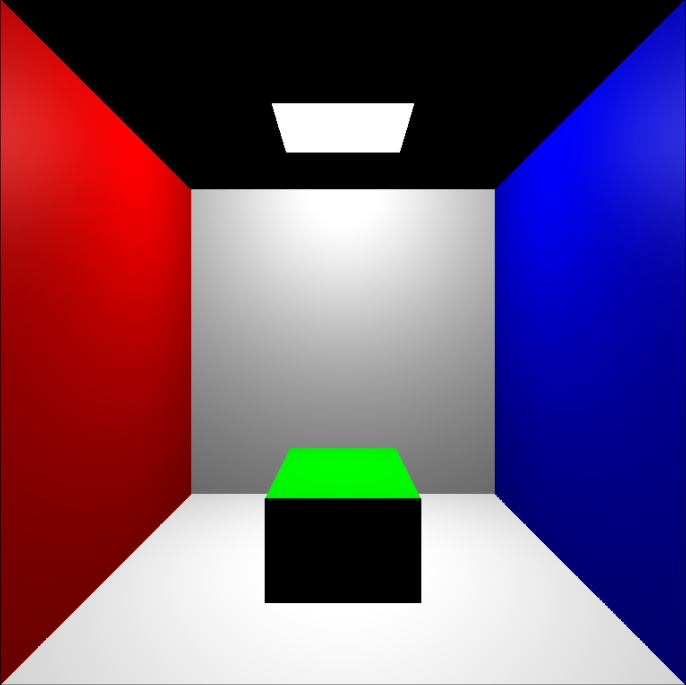
A simple lighting scene demonstrating Radiosity. At most two primitive objects will be in the room with multicolored walls.
To simulate Radiosity we must use the idea of heat transfer in physics and apply it to light.
The idea is that when heat(light) is present in a scene, it transfers it's energy to its surroundings.
The surrounding objects are then influenced by this energy and attain energy themselves and the process continues.
Now substitute 'light' for 'heat' and Radiosity comes into play. The light from a point-source or any source, influences
it's surroundings and they in turn 'light up' with energy. We decided to tackle Progressive Radiosity and that means
as each iteration happens, the sources of light become larger and larger in quantity and the scene gets more refined
Now this Radiosity has a number of pros and cons, but the most influential pro would be that we don't have to recalculate
our algorithm if the camera changes position. One expensive calculation is done at the forefront and that is all that needs
to be done to set a scene lit by Radiosity.
Mini User's Guide
Implementation
The process to go about creating a scene with Radiosity is conceptually simple, but the implementation is what really got us.
First we created the scene using three.js. Then we divide the meshes of our scenes objects into the exact same mesh except
higher resolution. Much like pixel resolution on a monitor from 800x600 to 1920x1080. Once that is done, our scene should
have a point-source light and ready to take radiosity.

As we start Radiosity, we must define which patches (mesh) have 'energy' or are emitters. We then give priority to the
patches with the highest values (sorting by light values). After we sort we go to each patch and from the respective
patches view, use z-buffer to see which other patches does it influence and allocate energy to said patches. Now to
simplify this task one can either use gathering or shooting method in conjunction with the hemicubes. As we are at
each patch, there will also be it's very own hemicube. The hemicube is placed on top of the patch and takes in (gathering)
or distributes (shooting) the incoming or outgoing light values, respectively. The use of a hemicube is to find the vector
of light that is influencing the patch. With this vector we can find out its theta and how much impact is the light acting
on our particular patch (gathering). Each hemicube has 5 'windows' and each are used to define the patches color (gathering).


