Homework
- Intake survey Do in class Mon, 2014 Jan 6.
- Turn in by e-mail by midnight Friday, 2014 Jan 10: Look on-line
for projects that might be interesting to design or build this
quarter. Look at sites like Pasco and Vernier for ideas about what
schools with money have in their labs. Look for do-it-yourself lab
equipment ideas on the web. Turn in an annotated list of URLs for
interesting sites as plain text, cut-and-pasted into e-mail to karplus@soe.ucsc.edu.
The annotation need not be extensive—a sentence about each web
site, telling us what project(s) it has information about should suffice.
I've collected student responses and started adding comments. Go look at what fellow students have found—there's some cool stuff there!
- Before 2014 Jan 15, look up how a spectroscope, spectrophotometer, or spectrometer works. Try to find some DIY versions.
- Turn in Wed 2014 Jan 22: Write up a design for an absorption photospectrometer that can produce plots of absorbance as a function of wavelength for wavelengths from 700nm down to 300nm. Describe the components, what properties they need to have, and how they fit together. Be as detailed as you can in the time you have (this is a one-week homework, so should take about 4 hours per person for a 2-unit class). Feel free to use web resources and the science library, but be sure to cite all your sources. This can be done in groups of 1, 2, or 3 people. Turn in a paper copy on Wednesday, with the names of everyone in the group on the paper. It would also be very useful if you could email me a PDF version of the file. If you have any questions, please e-mail the bmes-design-w14@soe.ucsc.edu mailing list, so that I can respond where everyone can read the answer.
- By Thursday night, 2014 Jan 23, e-mail your photospectrometer design to the class e-mail list, so that everyone can share the designs.
- For Monday, 2014 Jan 27, as individuals (not groups),
find a data sheet for the phototransistor WP3DP3BT.
Also, select a cheap photodiode that is available in the same size and shape
of package as the WP3DP3BT phototransistor and look up its data
sheet.
For the photodiode and the phototransistor, report the dark current, the voltage drop across the device (that would be collector-emitter saturation voltage for a phototransistor and the open-circuit voltage for a photodiode), and the sensitivity (current at 1mW/cm2 at λ=940nm, which is the wavelength where silicon photodiodes and phototransistors are most sensitive).
Find a plot of the spectral sensitivity of a silicon photodiode or phototransistor (it need not be from the data sheets you found—all the silicon photodiodes and phototransistors have similar properties, unless the packaging they are in filters the light).
We want to make a circuit so that the full-scale (5v) reading on the Arduino corresponds to an irradiance of 204.8μW/cm2 at 940nm, so that each of the 1024 steps corresponds to an increment of 0.2μW/cm2. Remember that 1000μW=1mW. (We may not be able to use the full range, as the circuit should saturate at a somewhat lower value, depending on the saturation voltage or open-circuit voltage of the photodetector.)
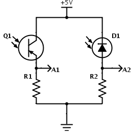
Update 2014 Feb 6: Q1 is intended to be an NPN phototransistor, not PNP as shown here!
For the circuits above, figure out what values of R1 and R2 to use to get the desired voltage range at A1 or A2. Look up what standard resistance values are available with 2% tolerance, and pick the nearest one. (Hint: Google is your friend for finding tables of information.)
In class on Monday, we'll try building this circuit and seeing how it works with the Arduino Data Logger.
- By Wed 2014 Jan 29, redo the homework originally due on Monday,
and turn it in on paper, typed, with the questions echoed and
answered in full sentences.
If you have any questions, discuss them on the class e-mail list. (I don't
want "I don't know" to come up for the first time in class—you
should have been asking for help over the weekend!)
Also for Wed, read the Wikipedia article on optical dispersion.
- By Mon 2014 Feb 3, design a colorimeter around the cuvette you picked up in class. Your design report should describe the function of the device, explain how it works, have a detailed drawing (with dimensions) of it, have a materials list of what is needed to build it, and give instructions for using it. If there are any computer components, an outline of the needed software should be included also.
- Before Monday 2014 Feb 3, get an Arduino board (I recommend Uno Rev 3, but any ATMega Arduino board should do), install Arduino software (more instructions in the Getting started guide), and start doing some of the on-line tutorials.
- For Wed 2014 Feb 5, find a through-hole (not surface mount) RGB
LED that is common-cathode, and design a circuit to power it from a
+5V power supply. Make each color be as bright as possible without
exceeding maximum current (you can leave a safety margin of up to
25%). Explain your design and how you sized the resistors for it.
I recommend using Digi-key's search feature (looking for RGB LED) to see what parameters are usually most important to designers. I recommend using Digi-key's free web tool SchemeIt for drawing a circuit diagram. They don't have an RGB LED symbol, but you can make one out of 3 LED symbols (I'd use variant 1 for that).
Bonus: find an RGB LED that is common-anode, and do the same design exercise with it. (If Digi-Key's search doesn't turn up a part, try using Google.)
- For Wednesday 2014 Feb 19 (no class Monday Feb 17), write an
Arduino program that will report over the USB cable once every two seconds
the status of pins
8, 9, and 10, whether that pin is high or low. The report should be
viewable on the Arduino Serial Monitor. It should look something like
8:HIGH 9: LOW 10: LOW
8: LOW 9:HIGH 10: LOW
8: LOW 9:HIGH 10: LOW
8: LOW 9: LOW 10: LOW
As a matter of common programming style, there should be a "block comment" at the beginning of every program telling what the program does (from a user's standpoint, not how it works from a programmer's standpoint), who wrote it, and when it was written. You may work on the programs in pairs (not larger groups), but the names of everyone who worked on the program should be provided in the comments at the beginning of the program.
Turn in a printout of your program. This program is simple enough that I don't need evidence of it working—for other class you may be asked to turn in the source code electronically, so that the graders can test the program, or provide input-output pairs that show evidence that the program is working correctly.
For those who find this program too easy, you can challenge yourself to do more ambitious programs:
- Read analog inputs from A0 through A5 and report the values.
- Accept characters from the USB serial line that change which pins you examine. (For example, getting the character '8' with Serial.read() might turn on looking at pin 8, and getting '*' might turn it off looking at pin 8.)
- Write a little control program that turns on the on-board LED (pin 13) when some combination of conditions is true and off when the conditions are false.